4 Encoders, 25 buttons. What to do with them? Considering how popular the F/A-18 is, an option can be a sort of minimalistic version of the UFC.

“Minimalistic” because 25 buttons are barely enough to build a the UFC but not the handy controls that come beneath it.
Also, in order to make this project more interesting, we will build an UFC plus some additional controls in the form of 3-way momentary switches.
The 25 buttons will be assigned as:
- 2x buttons: COMM1 and COMM2 radio selector knobs “pull” action;
- 12x buttons: 0-9 keypad + Cancel and Enter;
- 5x buttons: OSPs – Option Select Pushbuttons;
The remaining 6 buttons can be used to control 3x 3-way momentary switches. Although non latched, they can control for instance the ADF or the HUD Reject by moving up and down the switch lever. They can also be used to control the BARO/RAD Altimeter or the DAY/NIGHT HUD mode. Alternatively, they can control some of the Function Selector Pushbuttons. That’s entirely up to you.
A different yet interesting option can be the coding of a 3-way switch as a Master Mode selector in order to double the number of available functions.

Time to draw now. You can use pencil and paper or any software you want. I suggest LibreOffice Draw: it’s free, cross-platform and it’s also quite flexible.
Let’s start by drawing each component the same way we see it. Drawing them on a 1:1 scale will really help the next phases, not to mention if you want to to make this control box part of a wider plan (such as my poor-man-wannabe-cockpit).
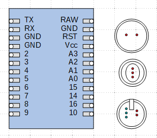
Drawing the pins of both Arduino and the various controls is a good idea and will help drawing the wiring diagram. I usually draw the diagram of each control and the duplicate and place them in a general disposition. It doesn’t have to be precise yet.
In case you haven’t noticed yet, the 3-way momentary switch has 3 pins; this is something we will have to take into account later.
The Button Matrix
I have already mentioned the Button Matrix. Let’s see how it works, considering a 3×3 example:

Easy right? Understanding a 3×3 matrix is indeed quite immediate but when the matrix gets really big the diagram can instead become a mess.
As a rule of thumb, if the matrix is square, every wire has to “touch” as many buttons as the dimension of the matrix itself.
The First Sketch
This is a quick sketch of our Control Box. Only two encoders will use the pushbutton function and they will be assigned, in our UFC transposition, to COMM1 and COMM2.

I haven’t talked about the size of the box yet and honestly there’s little point in it. Choose the box that you think will better suites your project by containing both the Arduino board and the wires and that will provide enough room to operate the switches without accidentally pressing any other.
In this case, a 170×140 [mm] box will do. Sometimes starting from the box is actually easier because not every size and shape is available on the market. A quick way to find an appropriate box is googling something like “abs enclosure“. Click here if you need help 😛