The guide I wrote about building a F/A-18 UFC-like control box based on Arduino uses doens’t need any modification to the firmware hence no coding whatsoever: just get the firmware, load up the libraries and write it. I wrote about the steps required to set up Arduino here.
But what if you want to divert from the guide, maybe adding an encoder or two? Adjusting the wiring diagram is easy: starting from the now well-known diagram, you just need to resize the button matrix. Once the diagram has been adjusted, the soldering and testing is done, it’s time to code.
NOTE: if you are in a hurry or know what you are doing already, you can grab the firmwares from the Download page.
Coding is easy!
Especially when you don’t have to code at all! In fact, as long as only variables such as the pins involved and the size of button matrix and the encoders are changed, there’s really not much to do.
Here are the parts of code you need to update to match your wiring diagram.
Definitions
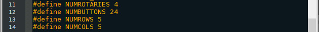
#define defines (no s**t Sherlock!) a constant value. The names are quite self-explanatory. NUMROTARIES and NUMBUTTONS define how many buttons and rotary encoders are present in your control box. The size of the matrix is defined by NUMROWS and NUMCOLS. The original author has decided to use only 24 buttons though, hence why NUMBUTTONS!=NUMROWS*NUMCOLS.
So, e.g. let’s change the code in order to make it work for my Radio Box (6x encoders, 3×3 button matrix):
#define NUMROTARIES 6

#define NUMBUTTONS 9

#define NUMROWS 3

#define NUMCOLS 3
Quite simple, isn’t it?
Matrix Buttons
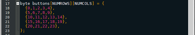
This bi-dimensional array may look complicated but it’s actually very simple: this is where each physical button is associated to the joystick output. If you don’t care about having buttons in a particular order (I do not. At all.) you can assign buttons in any order you want.
Following the previous example, a 3×3 matrix will look like:
byte buttons[NUMROWS][NUMCOLS] = {

  {0,1,2},

  {3,4,5},

  {6,7,8}

};
As I said, please note that you can put virtually any value there.
Rotary Encoders
The definition of the rotary encoders a slighly more complicated. In order to understand how they work we must first take a look at the struct that defines this bi-dimensional array:
struct rotariesdef {

  byte pin1;

  byte pin2;

  int ccwchar;

  int cwchar;

  volatile unsigned char state;

};
The struct tells us that the values of the array mean:
pin1 and pin2 are self-explanatory: they are the pins where the encoders are physically attached (→soldered).
cwchar and ccwchar are the joystick values sent to the PC when the encoder is rotated clock-wise or counter clock-wise. For instance, if cwchar = 12, when you rotate the encoder CW, your computer will show that the button number 12 has been pressed.
state is a variable that doesn’t concern us. Live it be!
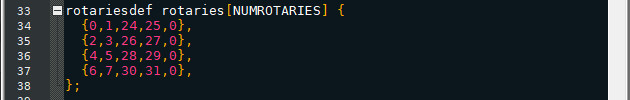
Our example (the Radio Box) uses 6 encoders, therefore the new array will look like this:
rotariesdef rotaries[NUMROTARIES] {

  {0,1,9,10,0},

  {2,3,11,12,0},

  {4,5,13,14,0},

  {6,7,15,16,0},

  {8,9,17,18,0},

  {10,16,19,20,0},

};
The Matrix
![]()
Easy stuff here, just tell Arduino which pins are part of the matrix.
The Radio Box uses a 3×3 matrix, therefore:
byte rowPins[NUMROWS] = {21,20,19};

byte colPins[NUMCOLS] = {18,15,14};
A last detail
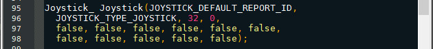
This is the initialization of the Joystick. See that 32? That’s the total amount of buttons included in your control box. I know what you are thinking: the aren’t 32 buttons here! And you are indeed correct: in fact you can change to value to match the number of buttons in your Control box. As long as that number is bigger than your buttons it’s not a problem. Windows USB Game Controllers test will show 32 buttons when you plug-in your box but you will be able to use just a part of those. Different story if your box has more buttons than 32 (my aux box has 70 buttons, my UFC has 80). In this case you have to adjust the value to match (or being highter than) the number of buttons of your box or you won’t be able to use most of them.
Howdy Karon,
I just recently found your website and have been binging your articles about creating your own panels.
I have wanted to make an HID Keyboard Unit for the Apache and have had issues writing my own code, as well as scavenging bits and bobs from the rest of the internet. I was able to make my panel work using MMJoy2 but I have been wanting to write my own code so I can expand upon it in the future.
I know very little about coding but have been struggling through it. I downloaded some of your .ino sketches in an attempt to dissect them to get my own code working. However, I have found I am running into the same problem with your sketches that I am with mine.
When attempting to verify and compile the code I have been running into this error:
(file path goes here)Org-UFC.ino:95:1: error: ‘Joystick_’ does not name a type; did you mean ‘Joystick’?
Joystick_ Joystick(JOYSTICK_DEFAULT_REPORT_ID,
^~~~~~~~~
Joystick
I’m hoping you’d be kind enough to help a guy out.
Thanks!
Hi mate, how are you? It sounds like a library issue. I checked the error message on Google, the first result mentioned something similar. See post #6.
https://forum.arduino.cc/t/joystick_-does-not-name-a-type-did-you-mean-joystick/658008/4
Shout if you still have issues 🙂