This is the first article of a series focused on delivering quick tips to my fellow RIO players. As mentioned many times already, I have no real life military experience so the vast majority of the contents come from manuals, practical experience and discussions with many military personnel I am so lucky to virtually fly with.
My first and only DCS module since 2008 is the Black Shark so my knowledge of fixed-wing procedures and avionics was very, very limited. Playing in the backseat of the F-14 has forced to learn and study a big amount of material and honestly, if you plan to learn how a radar and this kind of magic thingies work, then the F-14 is the module for you.
Before proceeding, make sure you have read the DCS: F-14 Manual thoroughly.
The antenna dilemma
The F-14 carries the outstanding AWG-9 radar but this is not the only source of information represented on the TID because the the Tomcat can receive data from the Datalink as well. The very first issue I run into when dealing with Datalinked contacts is that you need a lock from your own radar antenna in order to fire. In other words, you know that the target is there, but you don’t see it until you actually illuminate it yourself. Usually it’s not a problem, especially in BVR because the radar cone gets wider the further you get from the aircraft, but sometimes knowing the correct elevation angle and setting it quickly it’s crucial.
A couple of scenarios:
- A hostile contact is low enough to evade the lower limit of our radar cone. It is coming hot to engage us. The AWACS picks it up and relies its position to our TID. We need to be able to orient the antenna quickly to compensate the difference of altitude, in order to engage it before the hostile contact is able to fire.
- TWS Auto doesn’t work at the moment and, generally speaking, TWS Manual is often the best choice pre-launch (I use RWS way more but that’s another topic). As you know, TWS is limited in terms of azimuth and elevation so, in order to find and maintain the lock of widely spaced targets flying at different altitudes, a fine adjustment of the antenna elevation is required. We need to know the boundaries of the cone depending on their current altitude and distance.
There are many other examples but these two should give you an idea of why understanding the radar cone and the antenna elevation is very useful.
Building the Antenna Elevation model
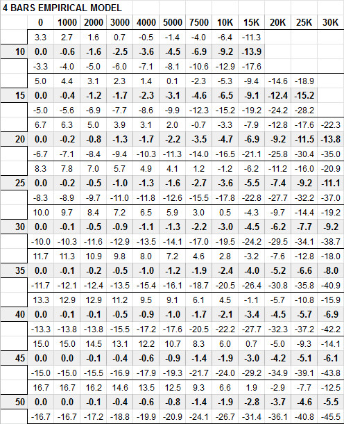
Since I didn’t find a chart describing the antenna elevation pattern I decided to build my own model. The goal is finding a general indication of where to slew the antenna in order to illuminate a target with my AWG-9 knowing only the distance and the altitude difference.
I made two more practical attempts by using data derived from the TID and a third one based on trigonometry. The reason why I tried three different approaches for the model was evaluating the impact of the TID lack of precision (both on the elevation angle and the altitude representation) and what practical effect it had. Moreover, I was concerned that the mathematical model was incoherent with how the limits are displayed on the TID, hence providing wrong results. On the other hand, a model based on the data from the TID itself should have been more coherent.
The conclusion is that the approximation of the mathematical model is well within usability limits even at 1 Bar and the lack of precision of the TID is negligible. Due to a number of compromises when I gathered the data, I am currently using (and still testing) the mathematical model discussed in the second part. Feel free to jump there if you want the results already.
The biggest issue with the first and second model is that at longer ranges and or low elevation the radar “hits the ground” and the TID returns zero, limiting the number of usable samples. The third module is instead unrelated to the TID readings therefore doesn’t suffer from this problem.

The first model is built by collecting data from the TID at predefined ranges and later used to create a projection to cover the range values not available on the TID.


I noticed that the first model tends to “fall short” at longer ranges when compared to the mathematical model. However, at longer ranges the cone is wider and that tends to offset the induced error very well. The reason is, probably, that the quadratic equation that approximates the antenna is based only on the initial readings from the TID. Further reading couldn’t be used due to the fact that the radar “hits the ground” as already mentioned.
The following is the model extracted by the results of the second method and it is based on data collected by using 0.1° degree steps. I used both higher and lower limit until one of the two “hit the ground” then interpolated the values to fill the remaining gaps.

Part II is focused on the mathematical model.

