Video
Basic Concepts
Though the various videos and articles of this series, we have seen how different versions of the Phantom II provide different information to the WSO. To keep things easy in this first part of the discussion, let’s assume that we know at least the Bandit Heading. Knowing the Bandit Heading, in fact, allows us to compute all the other relevant information: Target Aspect, or, probably more appropriately here, the Aspect Angle; then the Heading Cross Angle and the Cut, and so on.
Keep in mind that if the Bandit Heading is provided by the avionics, it will be in True, not Magnetic. Similarly to the Tomcat in fact, the WCS does not know the value of the Magnetic Variation at the target’s location. However, as long as the MagVar is not massive, it is usually not a big deal.
Note
Before proceeding, remember that the Navy tends to use Cut and Target Aspect (TA), whereas the air force uses, or used, Heading Cross Angle (HCA) and Aspect Angle (AA). As we know, these are the relative pairs of supplementary angles. Why? Dunno to be honest, whenever I ask the discussion turns into quite funny banter!
Starting from the Bandit Heading, we can use the BDHI to determine the HCA or the Cut. The indicator always points towards the heading of the aeroplane; therefore, we just have to look clock-wise or counter-clockwise, until we find the Bandit Heading. This is the HCA. On the other hand, if you prefer working with the Cut, simply consider the Target Reciprocal and do the same operation.
Sticking with the HCA, now we can add the Antenna Train Angle, and we find the Aspect Angle. This is because the sum of the internal angles of a triangle is 180°. Therefore:
Ergo:
Since we want the Aspect Angle, which is the supplementary angle of TA:
► AA = HCA + ATA
It goes without saying that the sign must be taken into account, more on this when we will do some practical examples.
Once we have the Aspect, we can plan the next step. The technique to use depends on the tasking, mission, loadout, fuel and much more. In general, the available documentation mentions only the simplest approaches, which tend to converge towards an intercept enabling front-quarter employment, or a stern conversion turn.
Front-Quarter Employment
The first technique we will discuss is straightforward and aims to improve the odds of a front-quarter FOX-1 or FOX-2, with or without VID. Since DCS is a game where IFF and coalitions are black and white, and brevities such as Outlaw or Spades are never used outside simulative groups, chances are that this will be a common intercept technique. Simply put, we want to grind down the Target Aspect or, vice versa, increase the Aspect Angle, to improve the odds of success of the AIM-7 Sparrow.
This can be done in several ways. If you are not new to my website, you may be familiar with the Cut and how it can be used to manipulate the angles. The Air Force being the Air Force, they do something similar with the HCA, but to me, it sounds less intuitive.
It all starts with the assessment of the Aspect Angle. Ideally, we want it to be high enough, but not 18, so 180°. The opposite, instead, if we consider the Target Aspect. In other words, we want the target to be as “Hot as possible” because this improves parameters such as Vc and the missile kinematics, but also not straight up our nose, as this reduces our manoeuvring room and therefore our options, and makes the target more likely to spot us with their sensors.
Consider the following simplified table to decide how to manipulate the angles:
| STATUS | ACTION |
| TA/AA Acceptable | Turn to Collision Course to capture the Aspect (Cut = CC) |
| AA too high TA too low |
Turn away from the target, placing it on the Cold Side of the display (Cut-Away) |
| AA too low TA too high |
Turn into the target, using the Collision Course ATA (CATA) as a reference (Cut Into Greater or Less than Collision). |
Once we are happy with the angles, we can lock them by turning to Collision Course.
When we approach the employment range, we should then turn to Lead Collision to help the missile hit the target. Lead Collision can be approximated as half of the ATA into the target. Intuitively, the missile is faster than the aeroplane, ergo it flies “more directly”, so to speak, towards the target.
The better way to use Lead Collision is following the ASE circle, which greatly simplifies the life of the crew. This is especially important when the restrictions imposed by the Interlocks switch are taken into account.
If we plan instead to employ an AIM-9, we should first verify that the version of the FOX-2 we want to use is “all-aspect”, as older Sidewinders, for example, could not effectively be employed beyond the rear quarter.
For an AIM-9 or equivalent, the angles are usually less important. A greater offset may even help to achieve a proper lock on the target.
Collision Course
Before moving to a more complex manoeuvre, let’s refresh two important topics, starting from Collision Course.
In particular, how we can set up Collision Course. For the F-14, I noticed and demonstrated using Euclid the properties of the Vectors displayed in the PPI-Scope that really help to set up CC in no time. However, the B-scope is different. As we know, a target on Collision Course does not drift on the scope. Therefore, we can observe the behaviour of the target over time to try and correct our heading and reduce the drift. However, this can be a long process, and we often won’t have the time. We need at least a starting point.
The following process is based on the properties of the intercept triangle when the two aeroplanes fly at the same speed. In this case, in fact, Target Aspect and Antenna Train Angle are equal, as the triangle is an isosceles. Therefore, CATA or, Collision Antenna Train Angle, equals the ATA, which in turns, is equal to the TA.
Looking at the intercept triangle sketch again, we can find the following relation:
CATA = TA
However, in “real DCS life”, so to speak, aircraft hardly fly at the same speed. I wrote a study backed by maths about how the Collision changes depending on the speed difference, which highlighted some interesting relations but, if we want to be direct and keep it elementary, we can start by using the relation described above, then adjust it from there.
Complete Computation
Let’s now see a complete computation, with the only known value being the Bandit Heading, with the goal of achieving Collision Course. The Fighter Heading is 015. ATA is 40L. This sketch is not precise down to the single degree, but close enough.
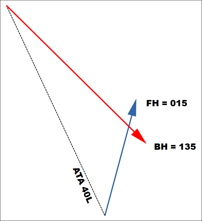
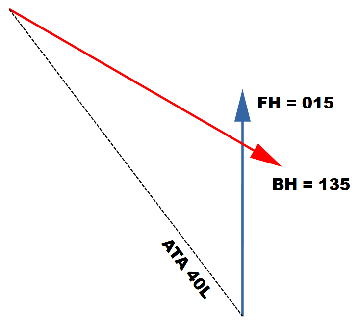
First, we determine the HCA from the BDHI. Since the BDHI always points towards the Fighter Heading, let’s re-orient the sketch to match it. Then, from 015 to 135 we turn right 120°, and this is our HCA.
Next, we find the Aspect Angle, defined as the sum of HCA and ATA. Therefore, 120 + 40 = 160R.
Let’s assume we are flying co-speed. If this assumption is incorrect, at least this gives us a starting point. Doing so, allows us to use the supplementary angle of the Aspect Angle as the Collision ATA.
Therefore, CATA = 180 – AA = 180 – 160 = 20
If we now do a simple empirical test by measuring the distances on the sketch, we find that they are very similar, and this proves that the computation was correct, as long as the aeroplanes were flying co-speed. If not, we can now observe the drift and adjust. Yes, there are formulas for this as well, but we are starting to get a bit too much into the details for a refresher.
The last point worth mentioning is the time factor: this computation, taken in a vacuum, is correct, but if the crew requires several seconds to draw these conclusions, the variables change, and the result may be incorrect.
Reciprocal / Zero-Cut / 180 HCA
One of the issues of the B-scope, is that it does not visually represent zero-cut or 180 HCA in an intuitive manner. On the PPI instead, a target flying parallel moves vertically towards the bottom of the scope. Why does this matter? Well, in primis is a good peculiarity, helpful to quickly build SA, but also because flying towards the Bandit Reciprocal has several benefits. For example, the LS is captured, meaning, it does not change as the range decreases. Also, TA equals the ATA. We can also eyeball the evolution of the angles over time, as they double as the range halves. Neat, right?
In conclusion, although the scope does not help as much as we would like, we can still find the Bandit’s heading, and then use the “+2 / -2 Rule” or other to find the reciprocal and carry on. As mentioned before, remember that MagVar is a thing.
Stern Conversion
So, let’s say we have launched our not-really-trusted AIM-7 from the front quarter. It missed because that’s what the Sparrows do. What do we do next? There are several options, you can blow-through and bugout, or we can stay and fight. In this case, let’s say we want to turn behind the target to employ an IR-guided missile. However, the present situation does not allow us to turn behind the target, so we need to make room first.
For simplicity’s sake, let’s do a tabula rasa and imagine we are not very close to the target, so we have time to think and act.
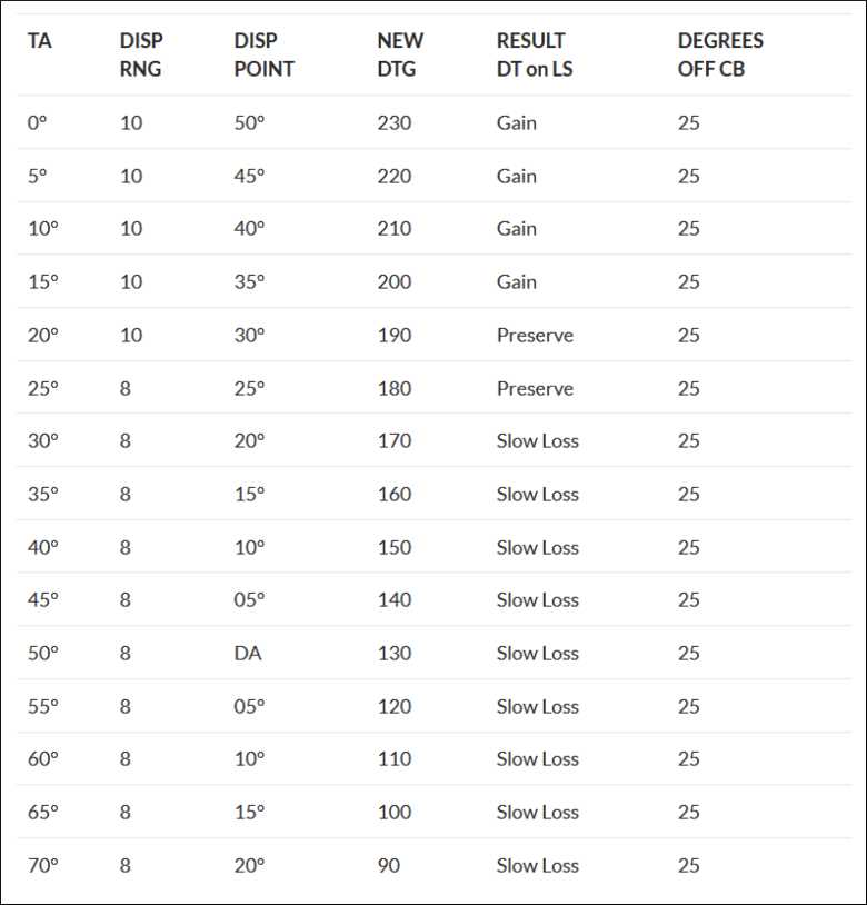
In primis, we determine the angles as we did earlier. But how much space do we actually need? The room is expressed by the Lateral Separation, which is the height of the intercept triangle drawn on the Target’s Heading.
British Phantoms used from 4 to 5 miles up to a dozen depending on the altitude. For the purpose of training, most documents use 40,000ft of Lateral Separation, or about 6.5 nautical miles, so I am sticking to that value.
Per sé, getting to the right spot to execute of the stern conversion is quite simple, all it all comes down to maintaining, creating or reducing the Lateral Separation.
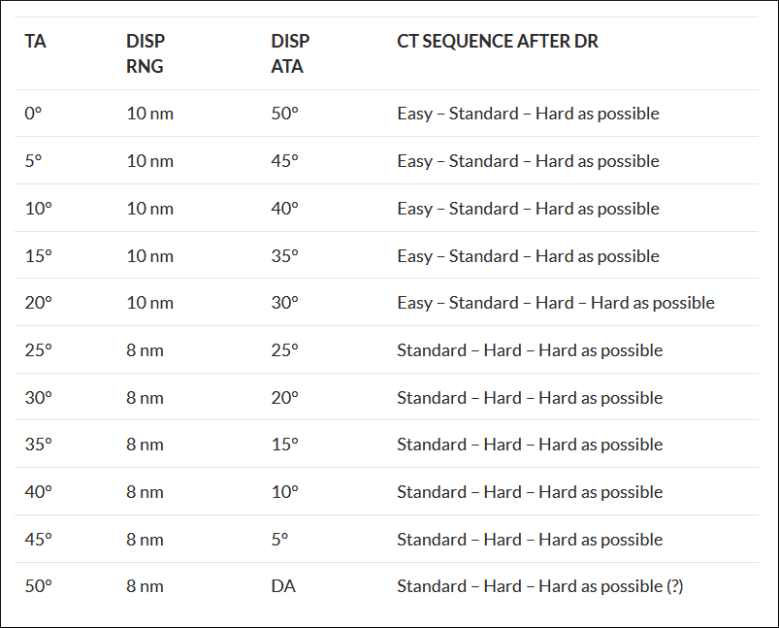
The following are a series of “gates” or checkpoints can be used as a template to follow: as long as those are respected, the Phantom should be at the desired place at the beginning of the Counterturn.
| Range | AA | TA |
| 30 nm | 165 | 15 |
| 20 nm | 160 | 20 |
| 15 nm | 150 | 30 |
| 10 nm | 140 | 40 |