
Related Articles
- INS Navigation: “Leap Frog” Operations;
- INS Navigation: Bullseye & Nav References;
- INS Fix Update: TACAN, GCI/Bullseye;
- INS Fix Update: Visual/Radar, GPS.
- What is the INS? Back to Basics – INS, Drift, and Navigation.
Although the F-4E-45MC belongs to a gone era, it can cover almost any role in any DCS server. Inevitably, it will be exposed to Bullseye-type information, either purposely or as a means of improving Situational Awareness. Given the restrictions of the AN/ASN-63 INS and -46A Nav computer, how can the Phantom II take advantage of such a data format? The answer is simple: a Spider Card, a topic discussed on this shores circa one year ago.
BULLSEYE
An established reference point from which the position of an object can be referenced by bearing (magnetic) and range (nautical miles) from this point.
The recent discussion about Leapfrogging showed how Target 2 can be used for navigation. This leaves Target 1 free for other purposes. In our case, the bullseye. It is worth mentioning that, from the aircraft’s perspective, this is meaningless: the directions provided do not depend on the type or purpose of the data set in the Target counters.
Scenario
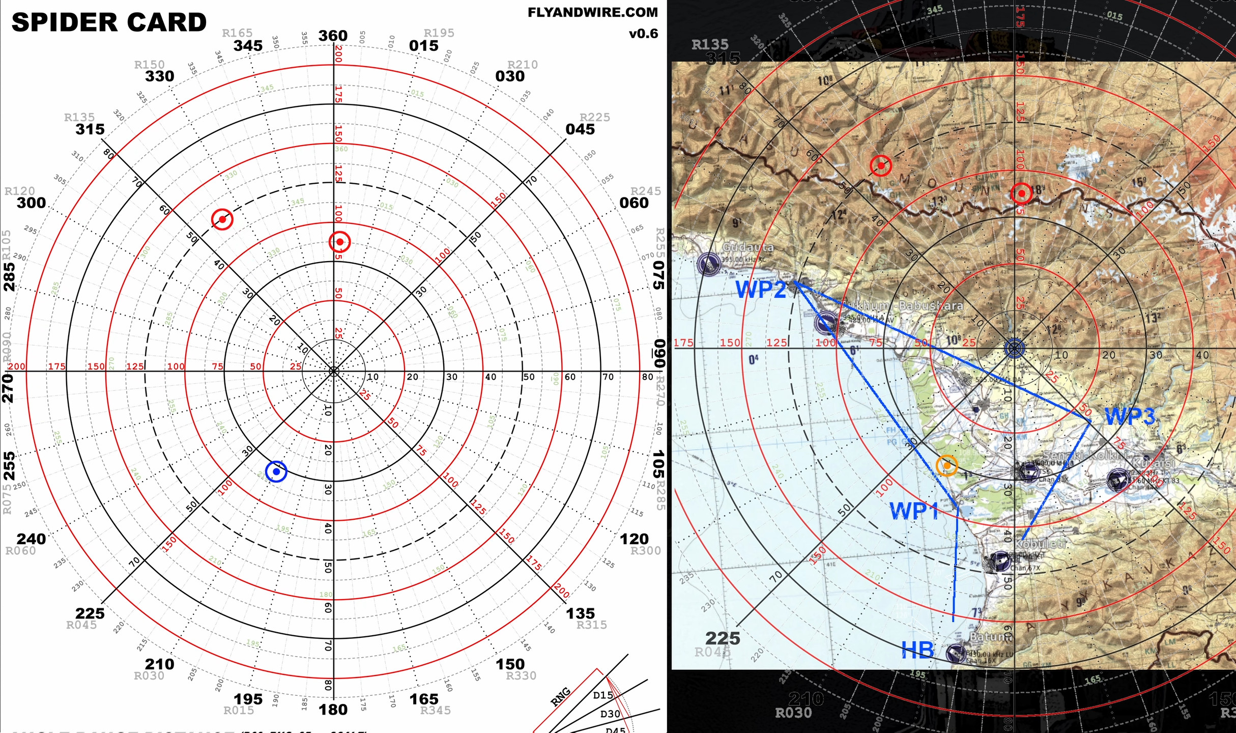
For the purpose of this article, the centre of the spider card represents the bullseye position.
In this scenario, the Phantom is travelling from Batumi to the town of Sukhumi via Poti, and then continues following the mountains. The destination might be a cap reference, another waypoint, or something else. Whatever the tasking might be, the crew should always try to monitor the radios to increase their situational awareness. Note that since the bearing is displayed from the Phantom II to the point, the crew must calculate the reciprocal value.
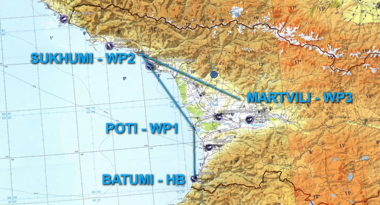
We start the scenario close to the Poti steer point, and the WSO is about to use the Leap Frog technique to update navigation information. At this moment, Target 2 is selected. The Nav Computer memory contains the latlongs of the Sukhumi waypoint. The first step is to input the correct coordinates in the Target counters. Later, when the F-4 is at the correct distance necessary to ease the turn and not overshoot, the WSO can switch to Reset and quickly return to Target 2. This procedure is described in the Leap Frog Operations video linked above.
Skipping forward, the Phantom is now en route towards Sukhumi. Target 2 is selected, and the Target counters can be freely manipulated.
Since the situation is quiet, the WSO can compute the Phantom’s position using the bullseye as the reference. By selecting Target 1, the BDHI shows the bearing and distance to the bullseye. The distance can be used as presented, but the provided angle is incorrect, and the reciprocal must be calculated or obtained on the BDHI.
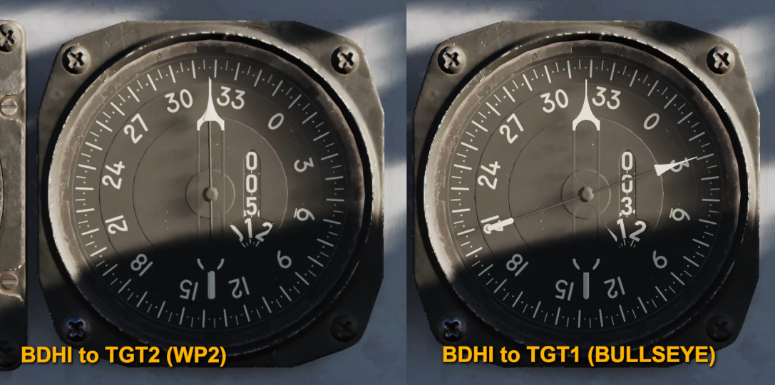
In this case, the BDHI indicates 030, 31 nm. The recip of 030 is 210. As mentioned, the WSO can use the “plus 2, minus 2” rule, or the BDHI itself.
After switching back to Target 2, the WSO can open the spider card and find their bullseye position. If you are using printed versions of maps and the spider card or want to spend some time editing images, a neat thing to do is to have them match the scale, thus creating a poor man’s moving map, in a sense.

Back to the bullseye, the WSO can now wait for or request a picture, depending on tasking, mission, etc. For the purpose of the discussion, I asked the AWACS for a Picture. Keep in mind that the controllers in DCS are often too basic to be useful.
The picture from the AI AWACS is as follows:
Picture. Two groups.
First group, bullseye 03/35, 30000.
Additional group, bullseye 324/50, 30000.
All the crew has to do now is plot the positions on the spider card or the map, and evaluate the situation.
The spider card can be used with other NAVAIDs, such as a TACAN station, following a similar modus operandi to facilitate navigation and improve situational awareness.
Possible Issues
Up to this point, everything sounds quite simple, and with a bit of practice, the process takes no time. However, there are a few possible issues. Two of the most common are the INS’s tendency to drift and the magnetic variation. The first is a problem only in specific situations or over prolonged flights. Also, a certain degree of imprecision is normal when operating hardware that, at its core, is more than half a century old. The second is intrinsic to the nature of our planet, and the crew should evaluate its relevancy. I ignored the issue in this article entirely, but depending on the tasking and ranges involved, 6.5° (MagVar in this scenario) can result in a surprisingly large error.
