
Video
This is, probably, the last part of this series focused on the radar basics and air-to-air and, probably, it contains some of the most interesting topics so far.
Radar Nutating Antenna Pattern
Let’s start with some peculiarities of the radar, in particular the Nutating Antenna Pattern.
This feature was used on older radars to improve their accuracy, and I am eager to see how Heatblur will depict it in DCS.
The nutating pattern is generated by manipulating the feed horn, which turns at a nonconstant speed to make the radar harder to jam. This feature increases the main beam width from 3.7° to 6.7°.
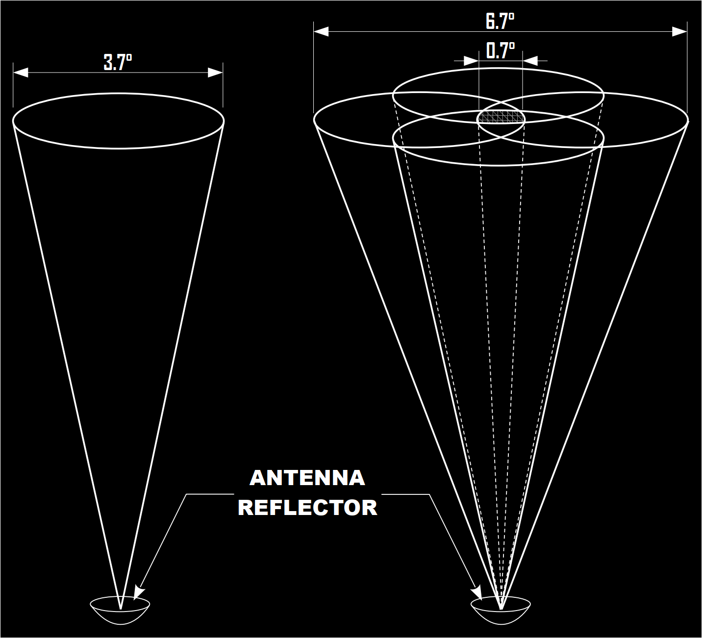
Nutating the radar beam improves angle tracking, and this is achieved by comparing the returns from the different lobes. For example, in the following image, when a target is in Position #1, the return has an amplitude signal proportional to the angular displacement from the centre of the radar beam. The radar processes and then drives the antenna to have the target in Position #2. Now the target is in the centre of the beam, and there is no additional antenna movement.
![]()
In case the target drifts away from the centre, the cycle starts again until the target is once more in Position #2.
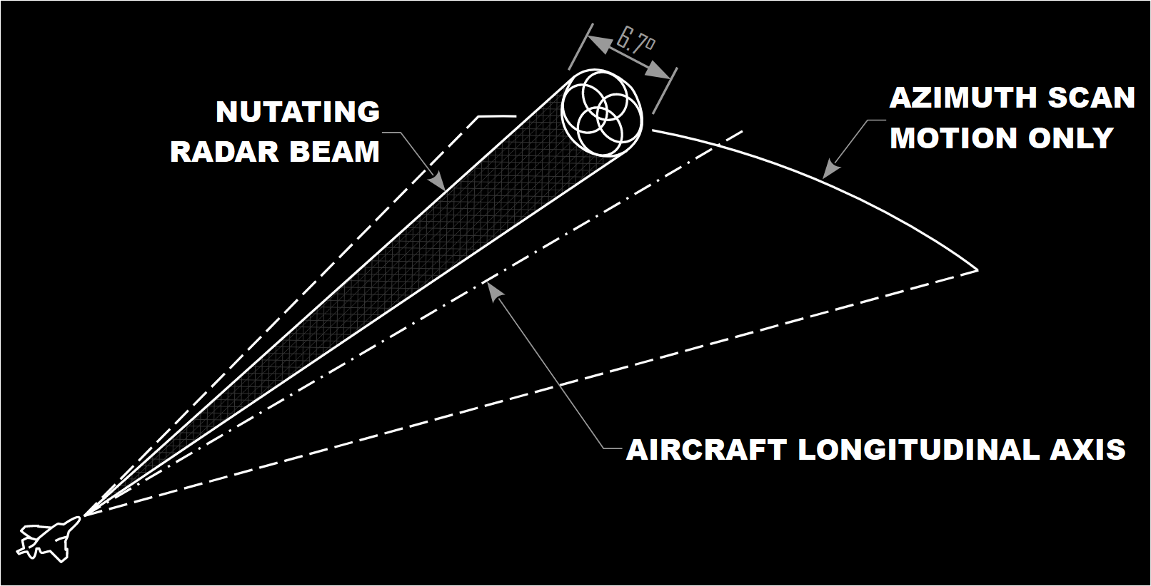
The other radar antenna operating pattern is the non-nutating. This mode is useful at long range, beyond AI ranges, so 100 – 200 nautical miles, and provides azimuth and elevation if the target’s position is more or less known. When the WSO tries to illuminate such a target, the non-nutating beam focuses the energy on the location, thus providing much better resolution. This technique is called “Spotlighting” and it is discussed further in this article. However, tracking or acquisition cannot be initiated in whilst Spotlighting a target.
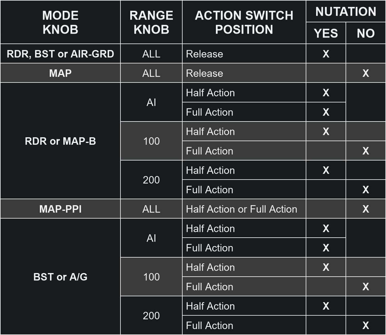
The following table shows the situations in which the radar nutating pattern is used:
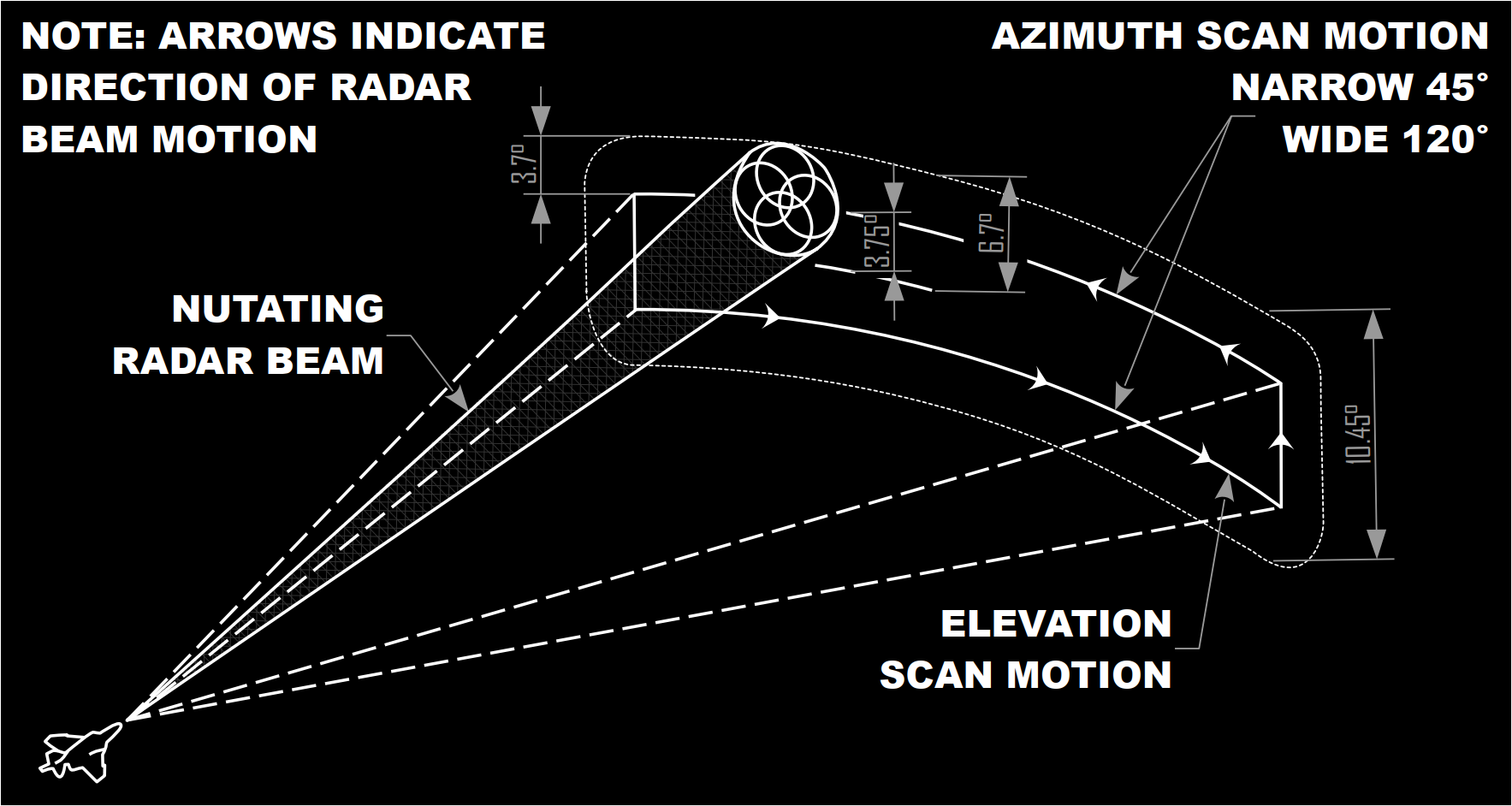
As discussed in the previous parts of this series, two elevation scan Bars are selectable by the WSO: 1 bar, or 2 bars. If the radar is not nutating, then 1 bar covers 3.7°. If 2 Bars are selected, after each azimuth sweep, the radar antenna is moved vertically by 3.75°.
If the radar pattern is nutating, then 1 Bar covers 6.7°, and 2 Bars cover 10.45°.
Since we are talking about the antenna and I have been asked about it, the Antenna Polarisation switch, the 3-way position located in the Radar Control Set Panel in the WSO’s office, usually operates in “LIN” mode. This mode offers the best detection performance under normal clutter conditions, but in case of bad weather or clutter, Circular 1 and Circular 2 may offer greater results.
Computer Automatic Acquisition mode
Let’s now move on with the CAA, or Computer Automatic Acquisition mode. Keep in mind that, as many other aspects of the F-4, it has slightly different characteristics depending on the upgrade of the Phantom II in use.
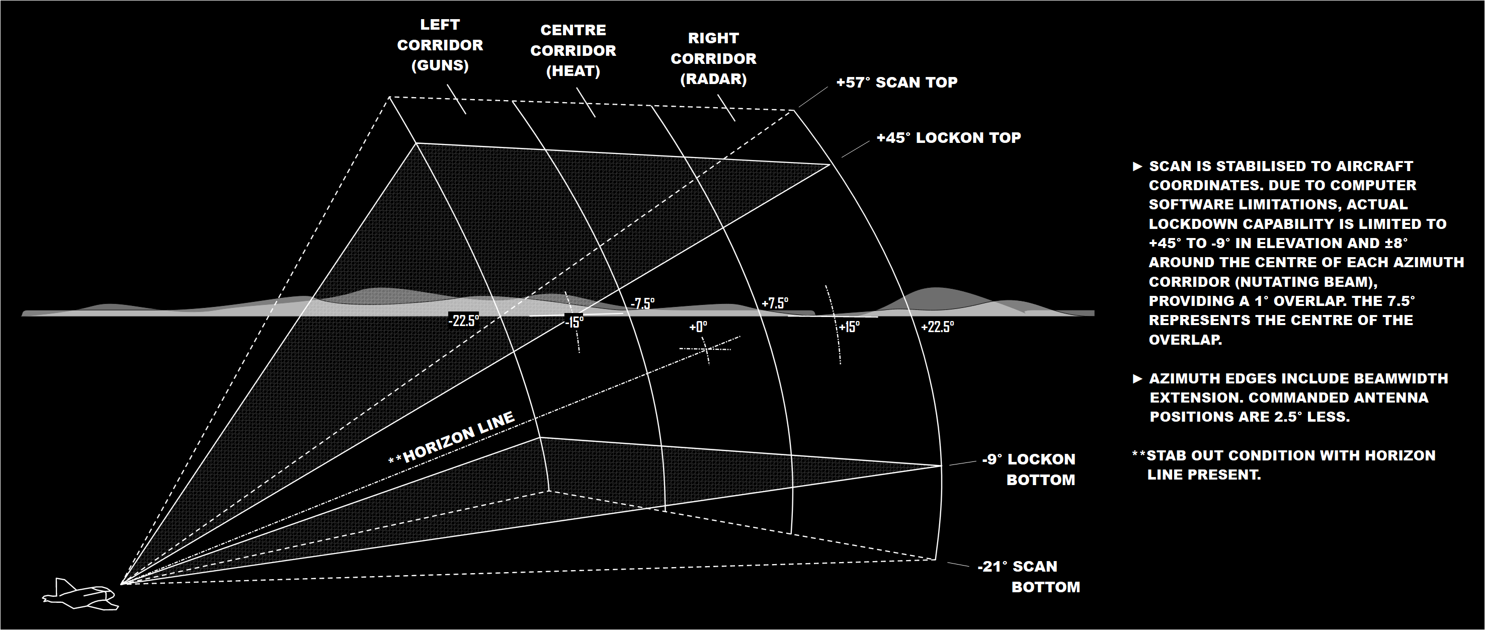
The purpose of the Computer Automatic Acquisition mode is to improve the radar detection and automatic acquisition performance. The sketch shows the radar volume covered by this mode. We can observe three vertical corridors, present only after a specific F-4 upgrade, and selectable via a switch located on the throttle.
The radar antenna operates automatically, and moves between +57° and -21°, but the actual lockon capability of the avionics is more restricted, and necessitates a broad buffer zone. This limits the automatic lockon region between +45° and -9°. The scan is quite rapid, as the antenna moves vertically, covering 120° per second.
As mentioned, the corridor is selectable, and the effect is moving the centre of the corridor to -15°, 0° and 15°.
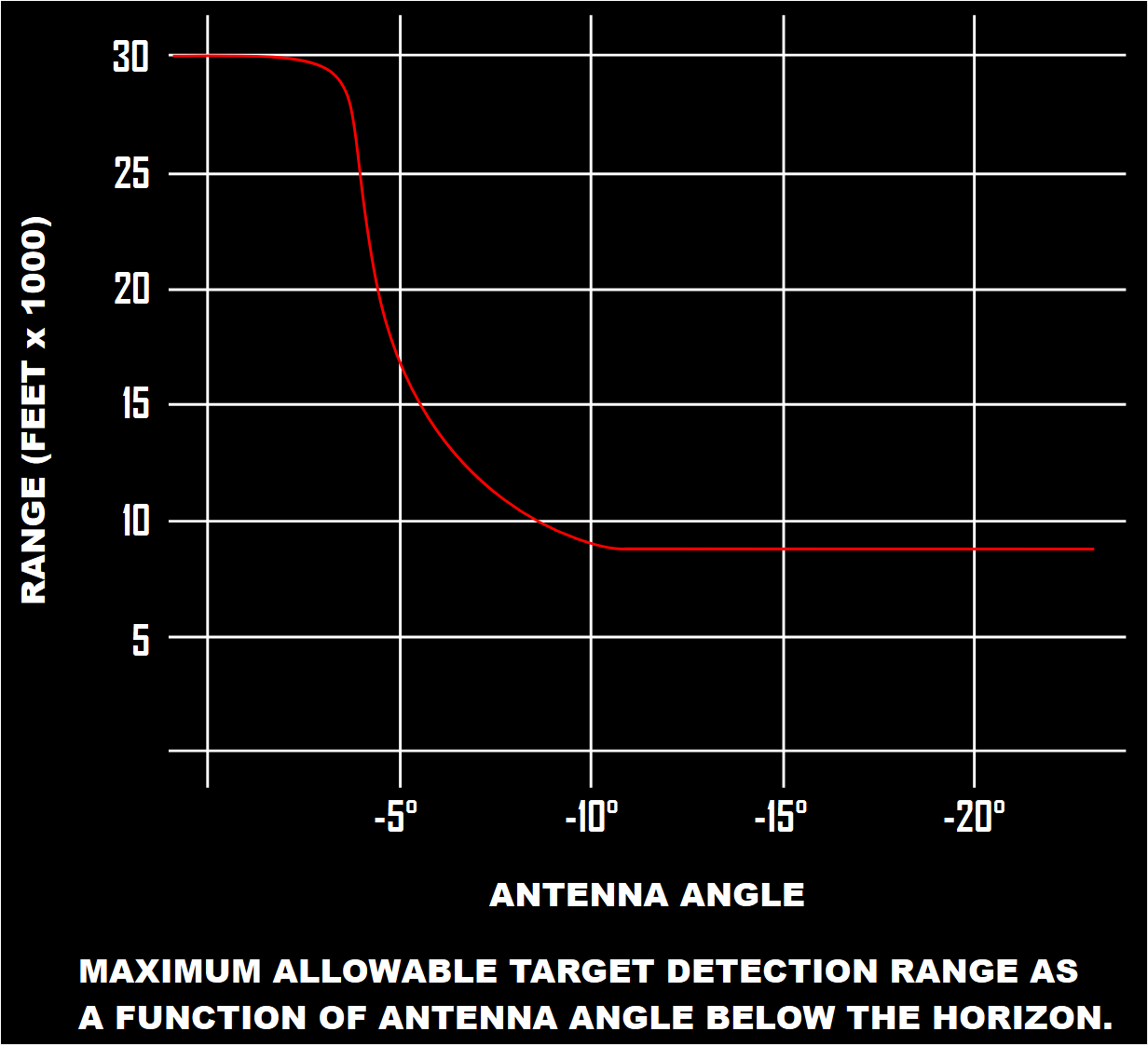
The CAA mode is surprisingly advanced, and includes an automatic range limiter when the antenna looks downwards, thus reducing the effective range, but also unwanted clutter and returns. This chart shows the mentioned range limitations versus range.
When the CAA mode is in operation, radar returns are automatically processed by the ACM computer, and the crew can maximise the chances of positive auto-acquisition by minimising any radar clutter return, for example by looking up, rather than downwards.
The Computer Automatic Acquisition mode is considered primarily an ACM mode, and thus the Hi-G function is automatically selected.
Antenna Stabilisation
The stab switch is located in the back seat, in the Monitoring Panel. This 3-way switch controls the stabilisation of the antenna, and the goal of this feature is maintaining the antenna at a defined angle with the horizon despite various manoeuvres and consequent pitch and roll inputs. In simple terms, without stabilisation, the antenna would be pointing up whilst we are climbing, or downwards when diving. Instead, unless external factors or crew inputs are applied, the antenna will remain at the same constant angle with the horizon.

The three options available are “Drift Out”, “Nor” and “Stab Out”. With the first two, the antenna is stabilised. Therefore, 0° of antenna elevation corresponds to the horizon, and the display shows the horizon line symbology. When tracking, both “Drift Out” and “Nor” show the target’s relative elevation on the EL Strobe.
With the switch in the “Stab Out” position, the horizon line is not displayed, and the EL Strobe the antenna elevation angle from the Phantom’s attitude, not the horizon. When tracking, the angle marked by the EL Strobe is the difference between the Phantom’s RBL and the target position.
RBL is the acronym for Radar Boresight Line, which indicates 2° below the fuselage reference line.
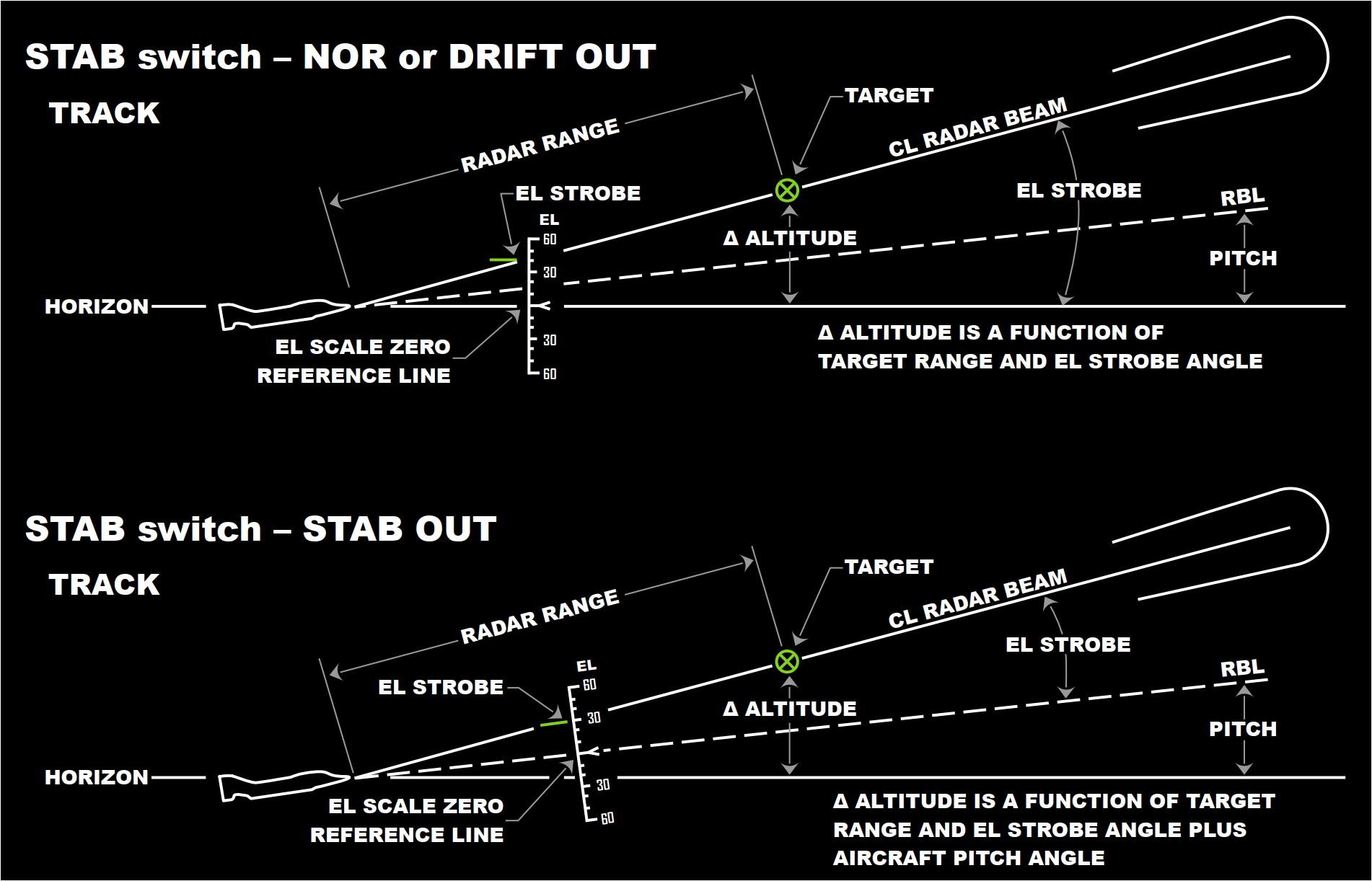
There are a couple of specific situations worth mentioning. In primis, in Air-to-Ground and Boresight modes, the RBL is the EL scale zero reference line regardless of the Stab switch position.
Next, in CAA mode, during acquisition the Stab Out condition is applied. Later, when tracking, the stabilisation is once again commanded by the Stab switch.
Elevation Strobe
The EL Strobe is nothing new to F-14 Radar Intercept Officers. Sometimes called “EL Indicator” in the Tomcat is used in a variety of situations, for example in conjunction with Pulse Radar modes, or Pulse Doppler Search, to determine, or at least approximate, the altitude of a target.
The F-4 Phantom II does not differ, and the EL Strobe can be profitably used in the same manner.
This chart offers both an example and a guide to determine the desired value. Alternatively, I am preparing a kneeboard page with a reference table to serve the same purpose.
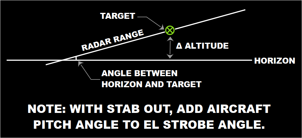
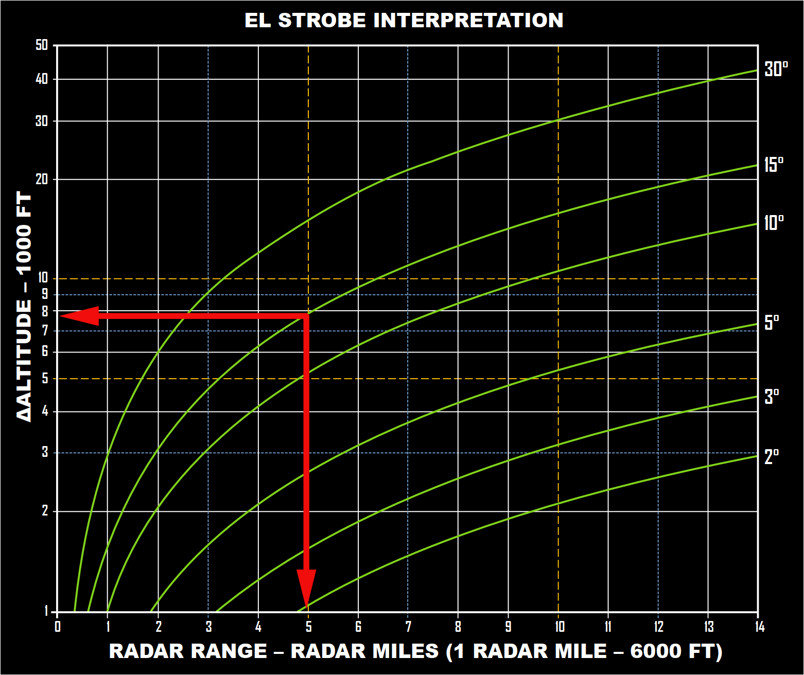
The interpretation of the chart depends on the stabilisation of the antenna. If activated, then the reference is the horizon. Therefore, all the WSO has to do is intersect the radar range in miles with the curve depicting the antenna elevation angle.
In this example, a target at 5 miles and 15° has a Δ altitude of circa 8000ft. However, if the Stabilisation is Out, then the reference is not the horizon any more, and the WSO has to add the aircraft pitch angle to the antenna elevation angle, before intersecting the radar range.
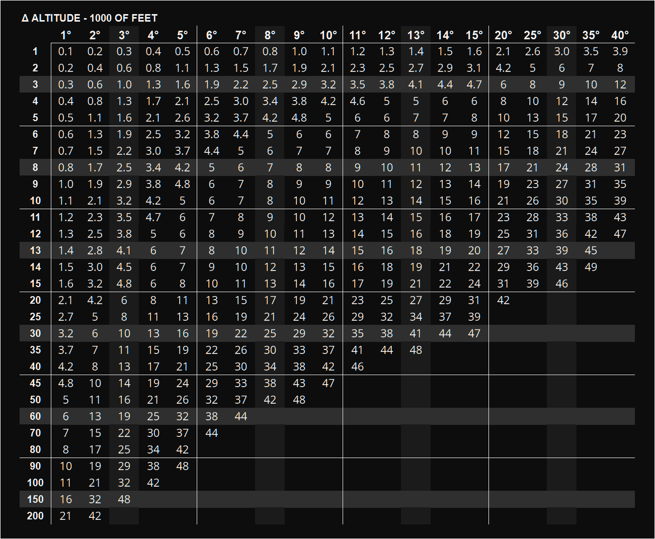
If we use my table, we have the same result, although I am still working on it, and I am still deciding the values at which I should start to round the altitude values. Eventually, I will add both this chart and my table to the F-4E Kneeboard pack I am putting together. A similar pack has been available for a very long time for the Tomcat, and you can download it from the dedicated page.
Other means take advantage of simplified mathematical relations described in my book in the Chapter dedicated to the Antenna Elevation Angle. The general mnemonic formula to approximate the Antenna Elevation Angle is Δ Altitude / (SR * 100). The 100 can be elided by using hundreds of feet in the altitude, as I doubt we will consider altitude lower than 100 ft. Therefore, the result is: Δ Altitude [h ft] / SR. This simple equation can be then used to calculate any of the three involved variables.
Δ Altitude [h ft] = Range * Antenna Elevation
Radar “Submodes”
During the overview of the radar, I mentioned that a number of “sub-modes” exist. This term is probably incorrect, as these modes are more peculiar functions triggered, or manually activated, only when specific radar modes are selected. Some of them have been discussed already, such as CAA.
The first improperly labelled “sub-mode” is AOJ, or Acquisition-On-Jam. This mode allows the WSO to use a source of noise or CW jamming as a target. It recalls the JAT mode in the Tomcat, and similarly, it allows angle-tracking but does not provide range indications. If the TISEO system is installed, the radar antenna may be slaved to the TISEO line of sight if it has achieved an optical lock-on.
The second mode is the familiar, HOJ, or Home-On-Jam. This mode is automatically triggered when a target starts jamming in the attempt of interfering with the radar tracking operations. Angle tracking works as in the AOJ mode, but range is also provided through operations on the memorised range and range rate. If the target reappears, and remember that burn-through ranges in DCS are arbitrary, the avionics automatically reverts to standard tracking.
Let’s move on to Boresight. “Cage” mode uses the Boresight radar mode when activated, placing the radar to 5 nautical miles range, and the transmitter to On and in Short Pulse. Cage mode can be used with automatic acquisition search modes, but its activation breaks existing locks. There are other caveats involving the weapon selected and TV mode, but those will be discussed in another part.
“Spotlight” has been mentioned already, and it is used when the radar range is outside the AI ranges, thus either 100 or 200 miles. Spotlight mode is enabled when the WSO uses the first detent of the action switch located on the Antenna Control to position the antenna in the area of interest, and then presses full-action. The effect is focusing the radar beam towards the desired location, providing much greater definition and, although automated tracking and acquisition are not available, allowing the WSO to manually monitor the target until AI ranges.
There are many other topics I wanted to discuss, such as the AIM-7 Speed gates, something similar to what we find in the F-14 Tomcat, but this functionality is not implemented due to the DCS radar simulation being too simplistic. However, I hope this will change in the future and if this is the case, I will cover this topic later.
