Guest Article by Peter from DCAF(Digital Coalition Air Force)
The Velocity Vector: Introduction
The aim of the lesson is to demonstrate to the pilot how the velocity vector is used on the TID(Tactical Information Display).
The velocity vector emanates from the centre dot of a track(whether a datalink track, or a radar track(only possible in Track While Search).
The velocity vector is a Euclidean vector, which in simple terms means that the angle of the vector shows the track of the contact, while the length of the vector represents the speed(or magnitude) of the track.
What the velocity vector represents is different in GND STAB(GrouND STABilized), and AC STAB(AirCraft STABilized), and respective pages will demonstrate their components.
The Velocity Vector: GND STAB
By default, the TID presents a top-down view of the picture.
When in GND STAB, the WCS stabilizes the display to the ground, meaning that the display is fixed while on aircraft moves on the display, with true North being used as ‘up’ on the display.
In TID ground stabilized mode the vector direction represents track true heading, and the vector length represents track ground speed.
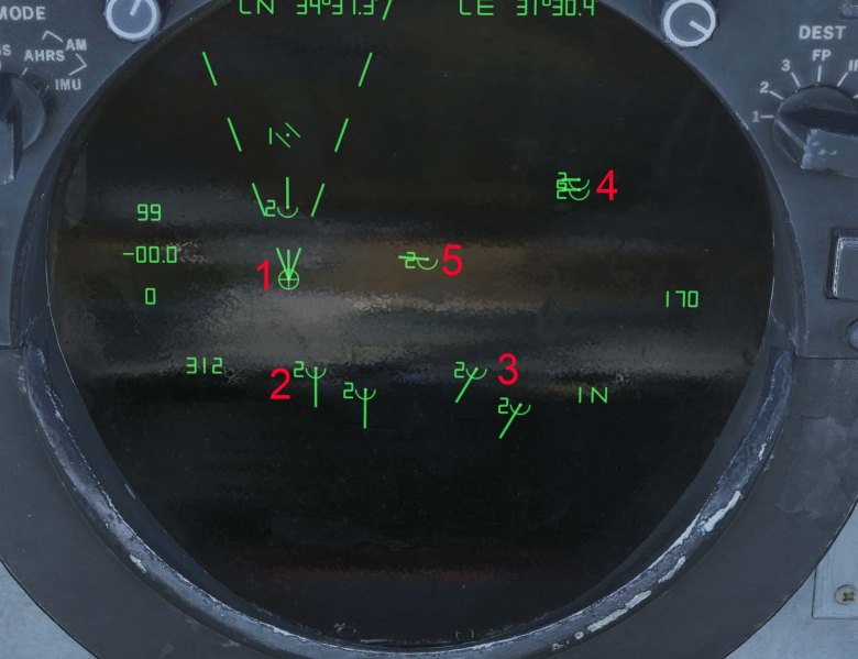
In the image below one can observe that ownship possesses its own vector, as do other tracks.

- Represents ownship vector. As can be seen, ownship is heading North, and the length of the vector is approximately 400 knots ground speed.
- Two contacts tracking South. In this instance, the vectors are slightly longer, representing a greater ground speed than instance 1.
- Two contacts tracking South West. In this instance, the length of the vectors are the same as instance two, showing their ground speed to be the same.
- Two contacts tracking West. In this instance, the length of the vectors are notably shorter than instance one, showing the tracks to have a slower ground speed than 1.
- One contact tracking West. Its vector is the same length as instance 1, showing its ground speed to be the same.
The Velocity Vector: AC STAB
While the components of GND STAB is reasonably straightforward, AC STAB is more complex.
When in AC STAB, the TID stabilizes the display to own aircraft, meaning that the display moves along with own aircraft which stays put on the display. Own aircraft heading is used as ‘up’ on the display. ATTK(ATTacK) functions in the same manner as AC STAB, but superimposes the attack steering symbology.
The manual defines that when ‘in TID aircraft stabilized and attack modes the vector direction represents track relative heading (to own aircraft) and the vector length represents track speed relative to own aircraft’.
In simple terms, what it means is that the velocity vector not only accounts for the track’s heading and speed, but also considers ownship’s heading and speed. This creates a vector that allows the pilot and RIO to visualize how the spatial relationship between ownship and the track will change in flight. This means that if ownship changes heading or speed, it will change the vector’s bearing and length from the track.
The full length of a vector on the TID is 1.5 inches, which represents a velocity of 1,800 knots.
Example 1:
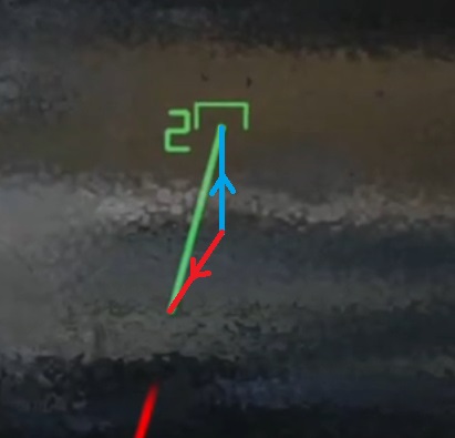
In the example below, a red dashed line has been superimposed, showing the movement of the track in relation to ownship.
One observes that as time moves the track is drifting down and left in relation to us.
Example 2:
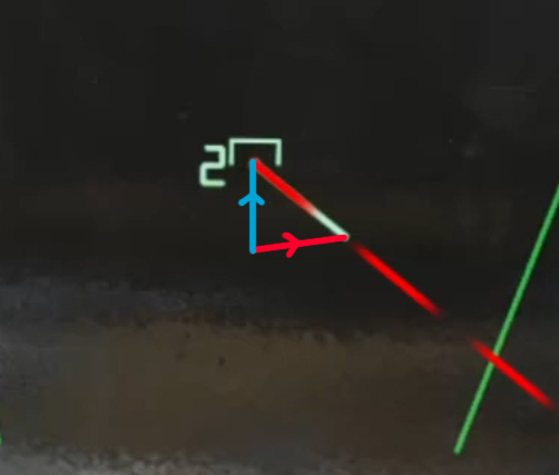
In the second example, another red dashed line has been superimposed, in which it can be observed that the track is drifting right and down.
Example 3:
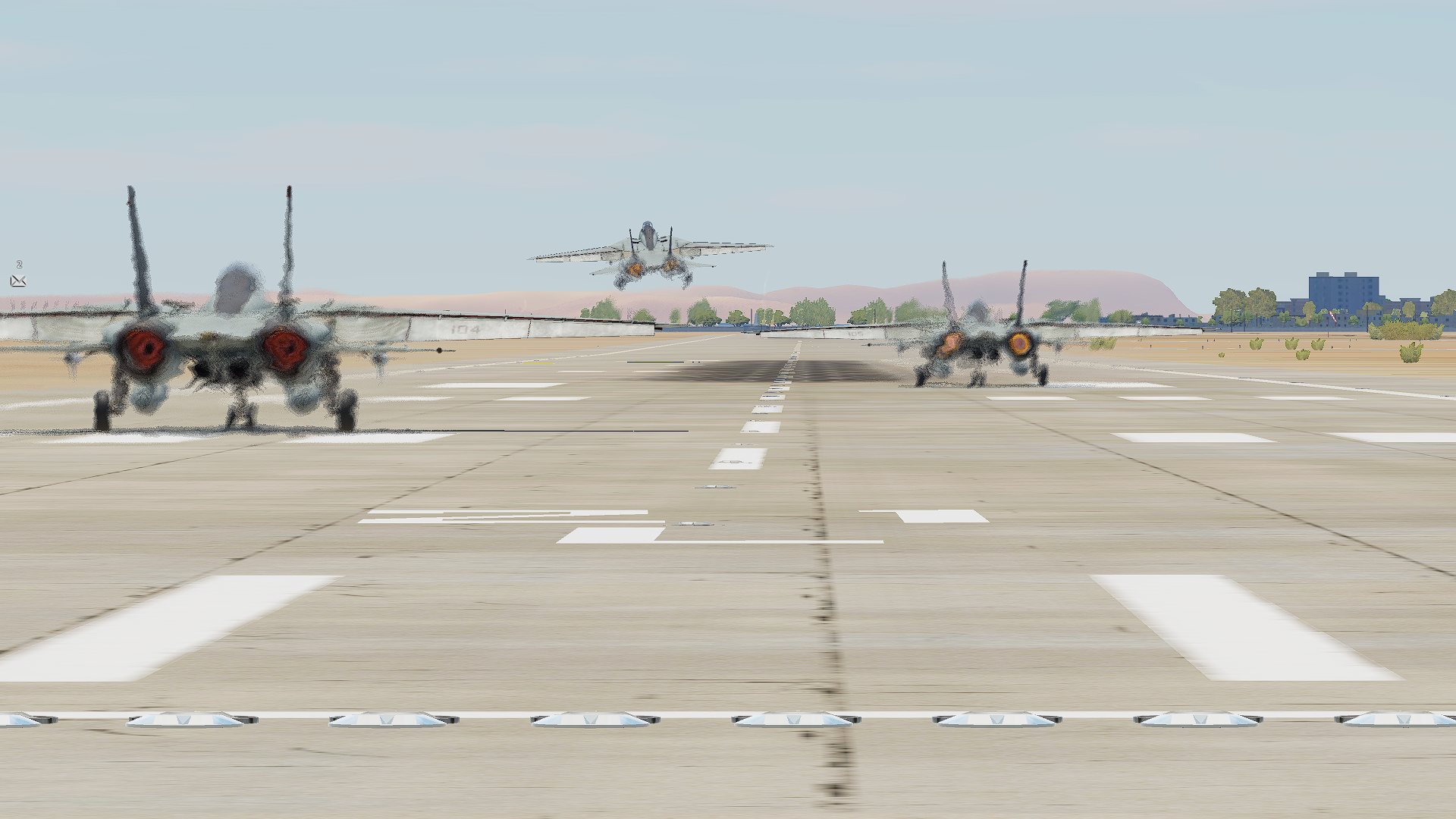
In the third example, the TID presents a datalink track. In this example, there is no visible vector present. This is because there is no change in the spatial relationship between ownship and the track. Both the track and ownship are heading the same direction, and at the same speed, and thus no (visible) vector.
Assuming the contact is forward of ownship, the following notes can be made:
- If the vector is pointed down or below the contact, it means the range between ownship and contact is closing.*
- If the vector is pointed up or above the contact, it means the range between ownship and contact is opening.
- If the vector is pointed left of the contact, it means the contact will drift left.
- If the vector is pointed right of the contact, it means the contact will drift right.
- If the vector is directly pointed at ownship’s symbol on the TID, it means a collision course has been established, in which the contact will drift into ownship.
* It can be easy to assume that just because a vector is pointed down, that the contact itself is flying towards ownship. As will be shown in example 2, it is possible(and frequent) that the contact is actually cold, but ownship still has a greater velocity, causing it to be a closing relationship.
Deconstructing the Velocity Vector:
In AC STAB, the velocity vector the aviator sees is the difference between the vector of ownship and track. Taking example 1:

The blue arrow represents ownship’s vector, and the red arrow represents the track’s vector; these are the vectors one would see when in GND STAB emanating from one another’s contact respectively. In this scenario, both ownship and track are moving at 600 knots ground speed, meaning that the length of one another’s vector is the same. By linking the vectors together, we can create a triangle and thus solve the velocity vector.
Since the TID is an AC STAB, ownship’s vector is always ‘up.’ The magnitude(length) of ownship’s vector is dictated by ownship’s velocity.
Assuming in example 1, ownship’s heading is 360, one can discern that the track’s course is approximately South-West.
Taking Example 2:

Once more, both ownship and track’s ground speed are the same at 600 knots. By knowing that ownship’s vector is always forward in AC STAB, and knowing our ground speed, one can imagine and superimpose ownship’s vector. Once done, we can solve and fill the remaining side of the triangle with the track’s vector. In this case, we find that the contact has an approximate target aspect of 100 – 110 degrees, and thus cold. However, due to ownship’s velocity, the velocity vector remains pointed downward as it remains in a closing spatial relationship.
Getting comfortable with the ‘look’ of a vector will help in recognising when a contact may be notching.
Notes:
- One can manipulate the vector by changing one’s own speed and heading.
- RWS radar contacts will not produce a vector, since radar returns are just contacts, and there is no track file. TWS and Datalink will provide tracks, however.
- The video examples above show instances where both ownship and track maintain the same respective velocities and courses. If either the track or ownship change their speed or course, the velocity vector will change, and thus the nature of drift.
Want to read vector lengths better? I have made a mod that adds a reference for vector length and respective velocity. You can download it here.
This guest article was written on behalf of DCAF(Digital Coalition Air Force). Interested in flying with an F-14 squadron? Check us out on our squadron page and Discord.
