Guest Article by Peter from DCAF(Digital Coalition Air Force)
Why use NAV GRID?
NAV GRID is a powerful tool to contextualize the picture in reference to YY/Bullseye. This becomes particularly important when receiving picture calls from a GCI/controller. Since the F-14’s Datalink can only show 8 tracks on the TID, it is frequent that bogey/bandit/hostile groups will be observed by AWACS, but not displayed on the TID. As a consequence, NAV GRID is the ideal tool to contextualise the locations of groups, and therefore their relationship to ownship, friendly assets and YY. If you’re a prospective RIO joining a structured flying group, NAV GRID will be an essential tool when managing situation awareness and leading a section/division.
Here’s a video introducing how picture calls are made if you’re unfamiliar:
Understanding NAV GRID:
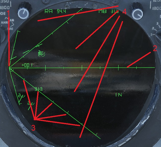
Like GND STAB, NAV GRID is orientated to a fixed coordinate/point. In this case, YY. YY is oriented at the edge of the TID, with the threat axis emanating across the TID.
- The point YY.
- The threat axis. Like GND STAB, the image is oriented with ‘up’ being true north. In this instance, the threat axis is set to 90 degrees(East). In this instance, the green line aligns with the threat axis, but due to sector selection this may not be the case.
- Emanating of the lines are tick marks. These tick marks are spaced 50nm apart, originating from YY.
- These areas are the sectors, which are divided up by the lines emanating out of YY. In this case, there are 4 sectors.
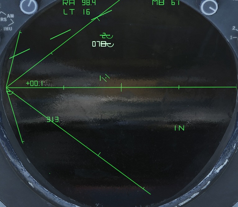
In the images below, one can observe what information is provided when a track is hooked:
1. In this circumstance, the RIO has hooked a contact(symbolised by its brighter colour). At the top of the TID, a read out is produced, with range and magnetic bearing, in relation to YY(that being a bearing of 67 degrees and 98.4nm away from YY). In addition, a voice code is produced on the left hand side of the track, in this case reading ’07B’. A voice code indicates bearing from YY in tens(thus 67 degrees becomes 07), followed by a letter indicating range(A = 0 – 50nm, B = 50 – 100nm, etc.). The Voice Code’s appearance alternates with the track’s altitude. The Target Aspect reading remains in relation to ownship, and does not account for YY. Otherwise, like GND STAB, the datalink track shows its speed and true course via the vector.
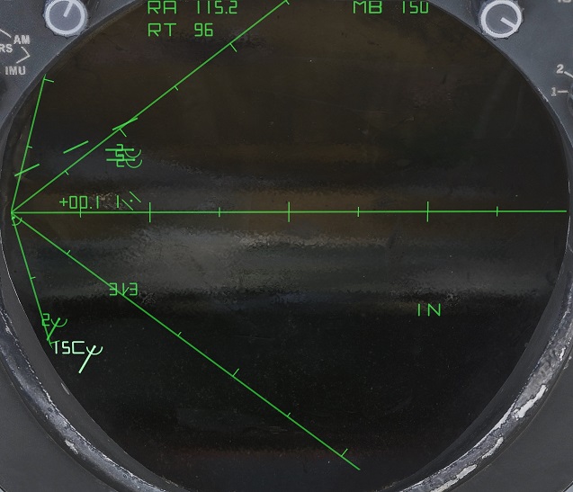
2. Another track is hooked. This time, the TID readout shows is to have a bearing of 150 degrees from YY, and is 115.2 miles. The voice code indicates a bearing of around 150, and is approximately 100 – 150 miles from YY.
Changing Threat Axis:
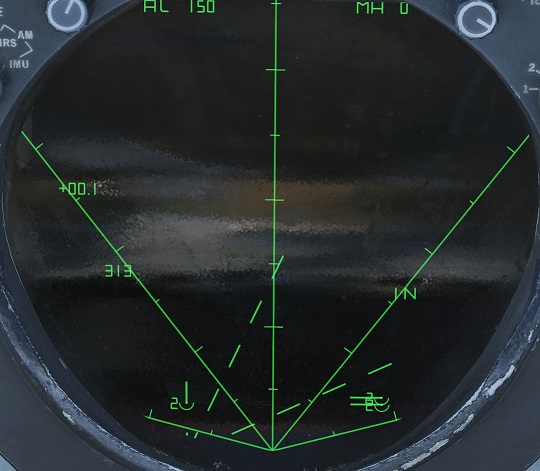
In the image above, the RIO has chosen a different threat axis of 360(North).
Grid Coverage:
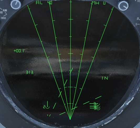
I this image, the RIO has set a grid coverage of 40. Note how the 4 sectors subdivide the grid coverage, and that datalink contacts are still displayed in GND STAB. The radar scan volume of ownship is also visible.
Different sector numbers:
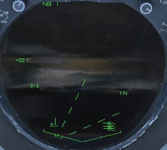
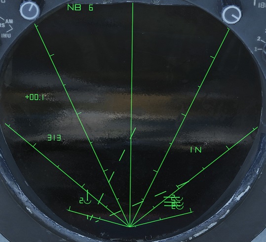
NAVGRID can have up to 6 sectors displayed. The left image shows 1 sector, and the right with 6 sectors, both within a 150 degree grid coverage.
HCU Offset:
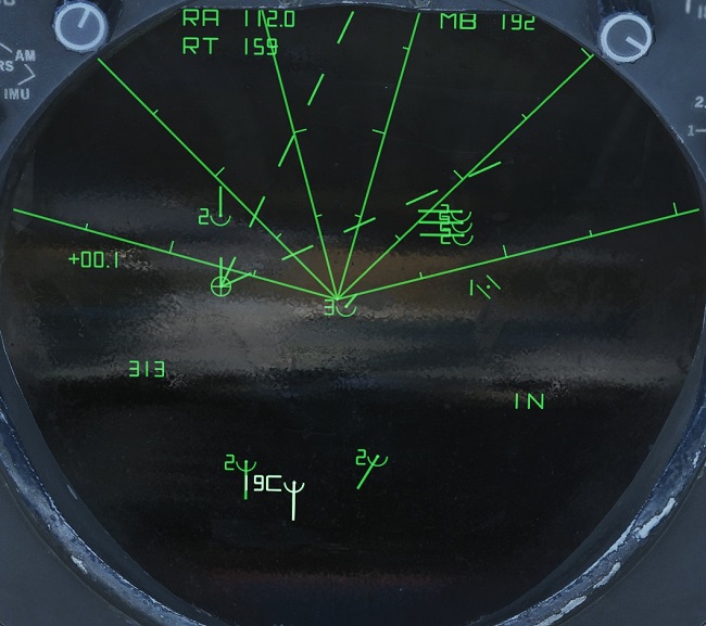
The final image shows when the RIO/mod is used to offset. Like GND STAB, hooking a point with the cursor and pressing the offset key will place ownship at that location, and thus all other information in relation to it. In this instance one can observe ownship to be approximately 60 miles North West, and additional datalink tracks South of YY.
If AC STAB or ATTK display modes are selected, only the voice code display functionality is retained, but in addition to the normal functionality the ownship symbol will always display its voice code.
Setting up NAV GRID (Pilot):
NAV GRID can only be set up from the RIO seat, and thus necessitates either using Jester.
When flying single seat, the following must be achieved in the Jester menu.
- Navigate to the Jester ‘Navigation’ menu.
- Open NAVGRID section, and select option 1 to enable NAV GRID.
- Either manually input the coordinates, or select a map marker. Typically, Bullseye is the frequent choice.
- Once Jester is complete inputting the NAV GRID’s coordinates, navigate back to the NAV GRID menu, and select either grid heading absolute or relative to define the threat axis.
- Next, on the NAV GRID menu, select the desired grid coverage, ranging from 0 – 180 degrees.
- Finally, select the desired number of sectors.
Setting up NAV GRID (RIO):
- Make sure TID mode is set to GND STAB.
- Set the Computer Address Panel(CAP) category knob to D/L(Datalink).
- Select ‘NAVGRID’ with the corresponding CAP Selector Button. The TID will now update showing the default settings of NAV GRID.
- First, input YY, via the LAT(1) and LONG(6) keys.
- With the HDG(8) key, set the desired threat axis.
- Next, set the grid coverage with the ALT(4), ranging from 10 – 180°.
- Using the HCU Offset, configure the picture on the TID to include YY, ownship, and points of interest.
This guest article was written on behalf of DCAF(Digital Coalition Air Force). Interested in flying with an F-14 squadron? Check us out on our squadron page and Discord.
